Large-format additive · 2022
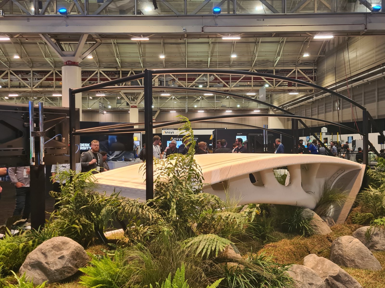
Dar Smart Bridge
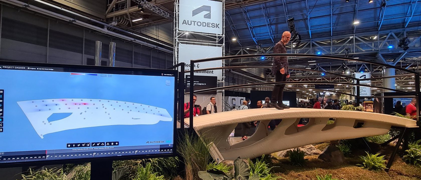
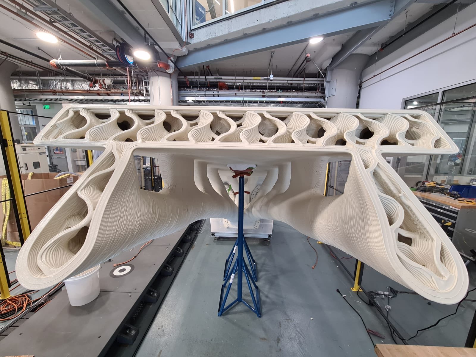
Two 3D-printed pedestrian bridges, a 2 metre prototype and a 5 metre single-cantilevered span, built with the engineering firm Dar. Both were printed from recycled PETG and glass fibre as large-format extrusions on a six-axis arm riding a linear track, instrumented with embedded strain and fibre-optic sensors, and exhibited as structures the public actually walked across.
- Role
-
- Designed and set up the work cells
- Integrated the Strangpresse extruder onto the arm
- Integrated the safety systems
- PLC programming
- Toolpath generation
- Material analysis
- Robot and sensor programming
- Fabrication supervision
- Team
- Dar, with the Autodesk Technology Center, Boston
- Stack
- ABB IRB 4600 on an IRBT linear track, Strangpresse extruder, RobotStudio, PowerMill, Faro Focus scanning, Project Dasher
- Timeline
- Scope agreed June 2020 · 2 m printing March 2021 · 2 m debut at IRF November 2021 · 5 m printing July 2022 · 5 m debut at Autodesk University September 2022
- Read more
- Engineering a Bridge that Designs and Builds Itself · Putting the “Smart” into the Dar Smart Bridge · Dar · VoxelMatters
Printing it
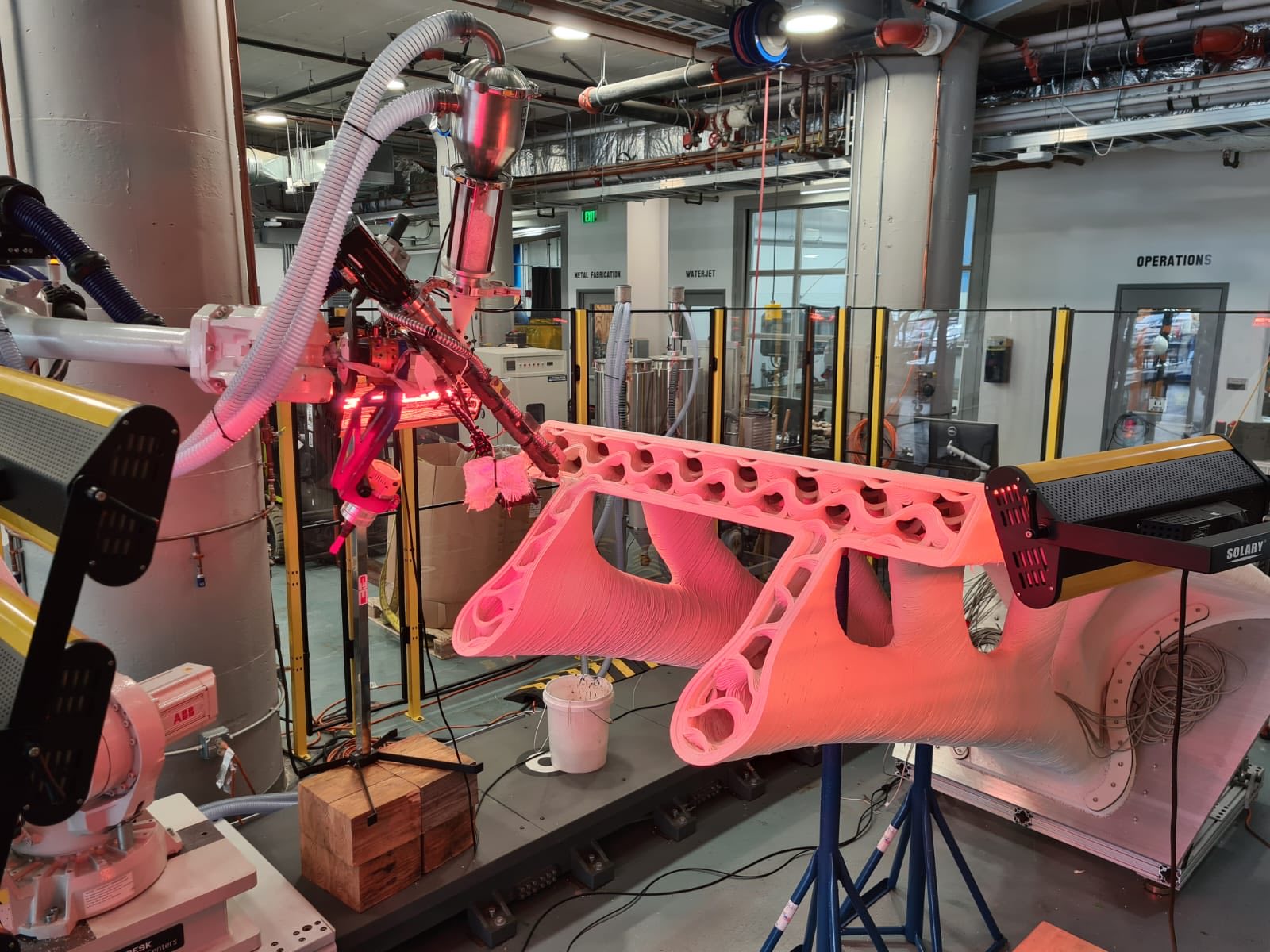
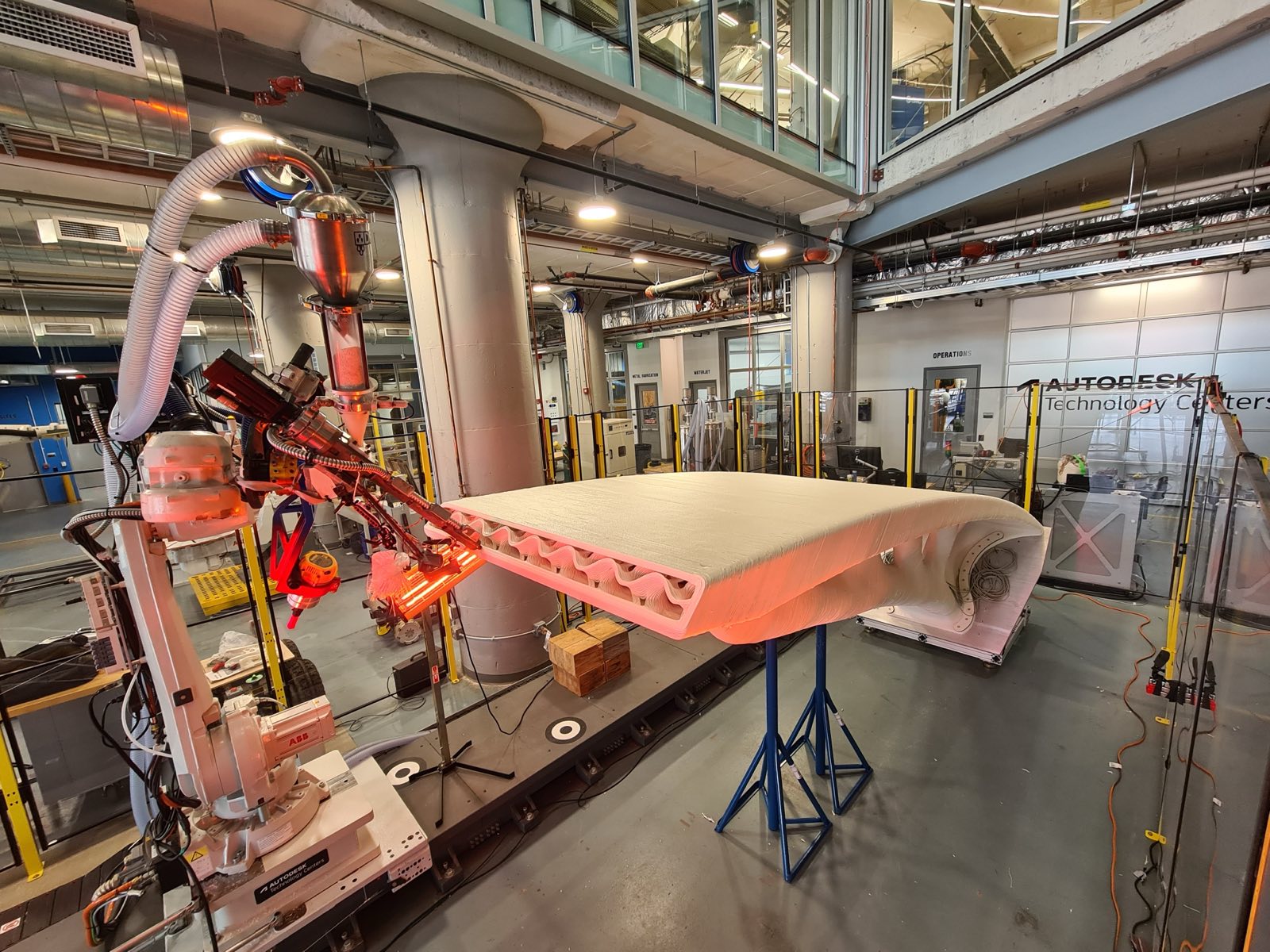
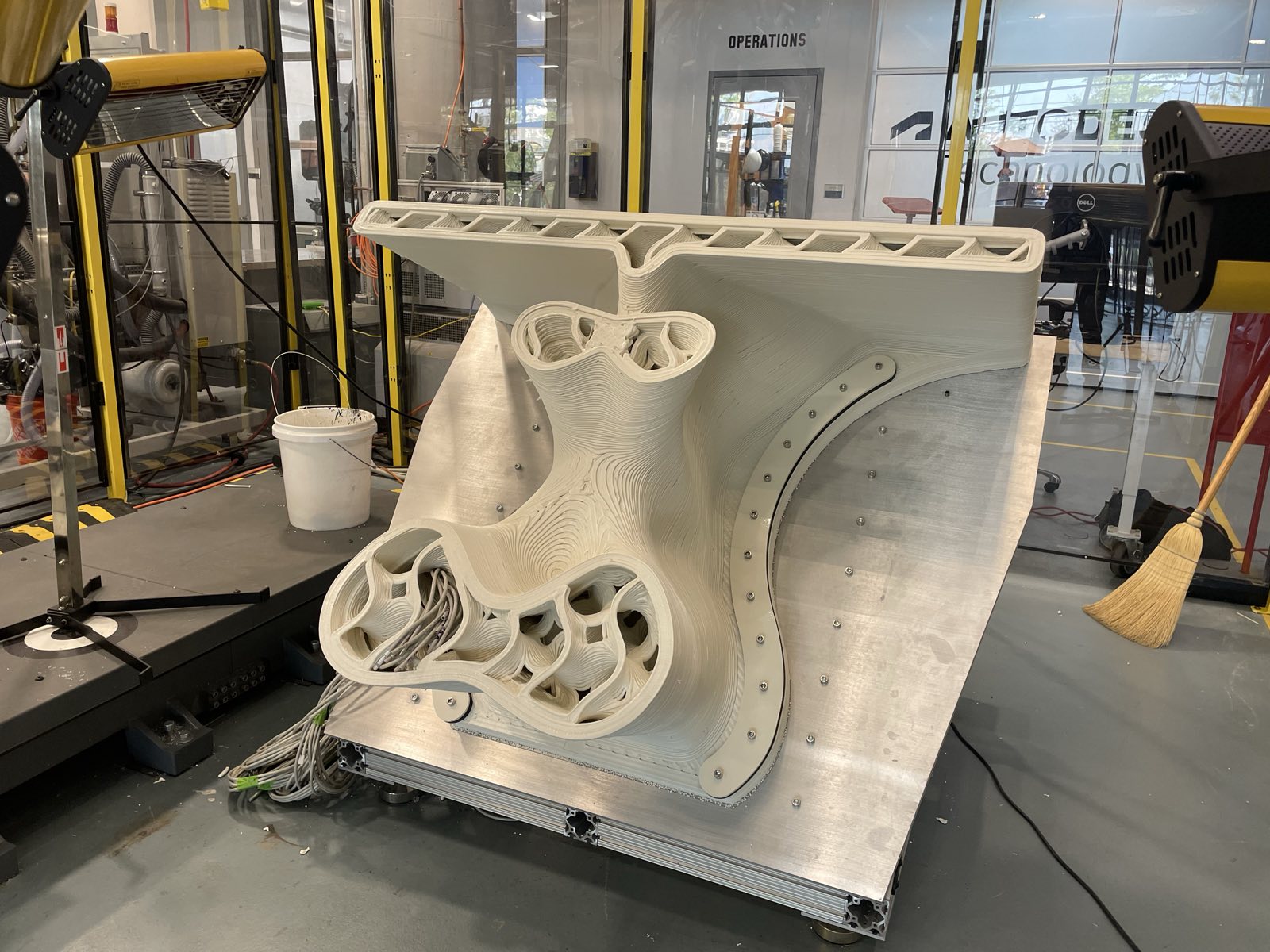
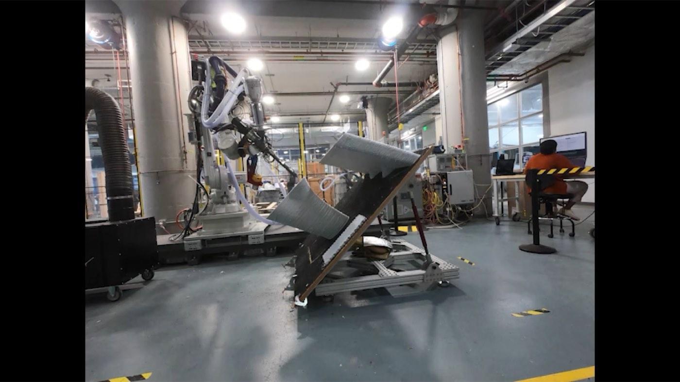
The spans were printed in continuous beads on an ABB IRB 4600 riding a linear track, with a Strangpresse extruder on the flange. Parts of the geometry were printed on an angled bed rather than flat. That keeps the bead perpendicular to the surface where the structure curves, at the cost of a much harder setup.
Material selection was its own research track: tensile strength along and across the print direction, melt and glass-transition temperature, maximum extrusion speed, UV and ageing behaviour, recyclability, and bead quality all had to land at once.
Designing for the process
The geometry was generatively designed against what the printer could actually do, not the other way round: a maximum overhang angle of 45°, a minimum element thickness of 32 mm, and a fixed print direction. Toolpaths came out of the Fusion manufacture workspace through a robotics add-in that emitted native robot code.
Instrumenting it
Sensors went in during the print rather than being bonded on afterward: strain gauges and fibre Bragg grating (FBG) sensors placed at structurally meaningful points, feeding a live model of the span.
Interlayer temperature was monitored throughout the print, because bond strength depends on how hot the previous layer still is when the next one lands. Above 110 °C was the target; 80–110 °C a warning band; below 80 °C a risk of a weak interlayer bond.